- Full integration in RFEM/RSTAB including import of all relevant internal forces
- Intelligent presetting of flexural buckling-specific design parameters
- Automatic determination of the distribution of internal forces and classification according to DIN 18800, Part 2
- Optional import of buckling lengths from the RF-STABILITY/RSBUCK add-on module. For this, a comfortable graphical selection of the relevant buckling mode is possible
- Optimizing Cross-Sections
- Optional calculation according to both design methods of DIN 18800, Part 2
- Automatic determination of the most unfavorable design location, also for tapered members
- Check of c/t-limit values according to DIN 18800, Part 1
- Design of any thin-walled RFEM/RSTAB or SHAPE-THIN section for compression and bending without interaction according to the elastic-plastic method
- Design of I-shaped rolled and welded sections, I-like sections, box sections, and pipes subjected to bending and compression with iteration according to the elastic-plastic method
- Clearly arranged, comprehensible design checks with all intermediate values in the short and long forms
- Parts list of members and sets of members
- Direct export of all results to MS Excel
- A manual with manually calculated examples
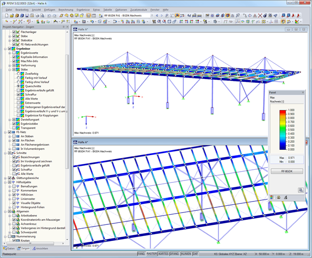
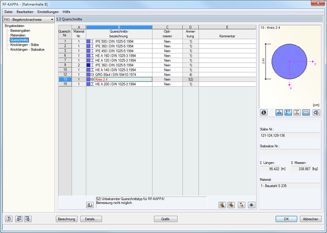
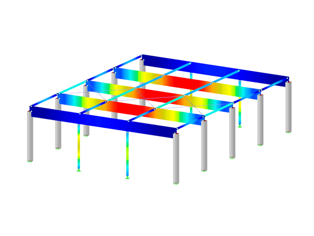
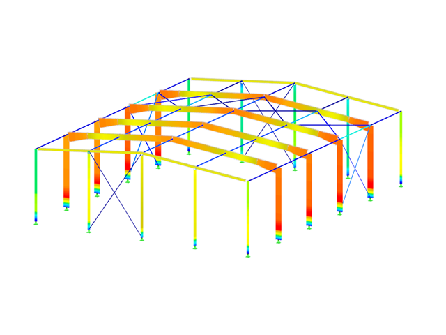
After the design, the results are displayed in different windows sorted by cross-sections, members, sets of members, or x-locations. The corresponding cross-section graphic is always displayed with the result values in tables. In RFEM/RSTAB, they are highlighted by different colors in the structural model. Critical or oversized components can be identified at a glance. You can modify the colors and values assigned.
Result diagrams of a member or a set of members ensure targeted evaluation. It is also possible to represent all intermediate values.
The masses determined during the design are displayed in parts lists for both members and sets of members.
Furthermore, you can export all result tables to MS Excel or in a CSV file. A special transfer menu defines all specifications required for the export.

- Design of five types of seismic force-resisting systems (SFRS) includes Special Moment Frame (SMF), Intermediate Moment Frame (IMF), Ordinary Moment Frame (OMF), Ordinary Concentrically Braced Frame (OCBF), and Special Concentrically Braced Frame (SCBF)
- Ductility check of the width-to thickness ratios for webs and flanges
- Calculation of the required strength and stiffness for stability bracing of beams
- Calculation of the maximum spacing for stability bracing of beams
- Calculation of the required strength at hinge locations for stability bracing of beams
- Calculation of the column required strength with the option to neglect all bending moments, shear, and torsion for overstrength limit state
- Design check of column and brace slenderness ratios
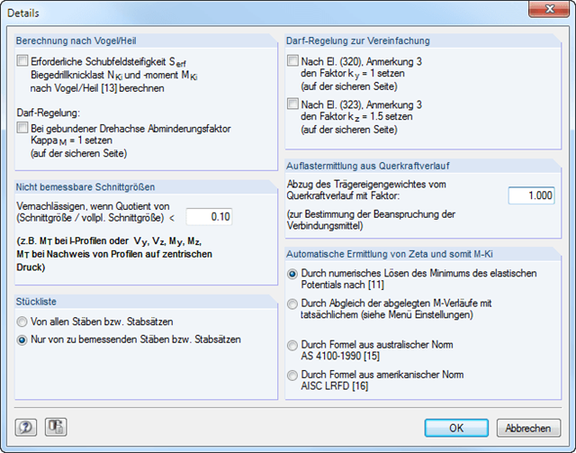
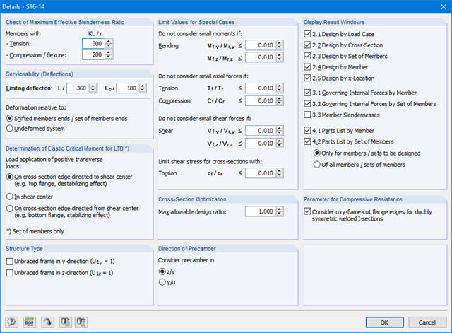
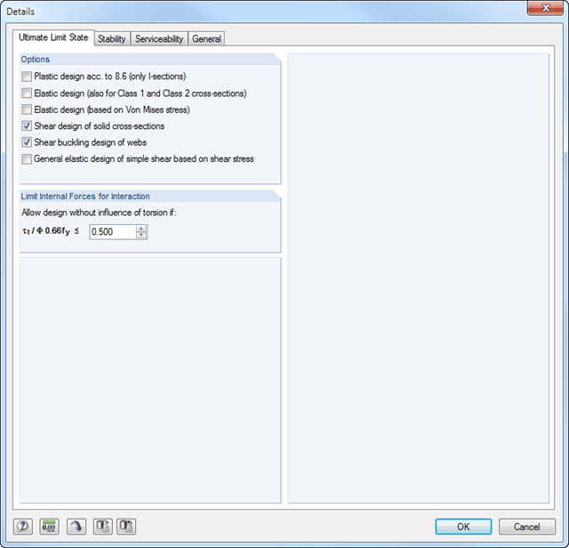
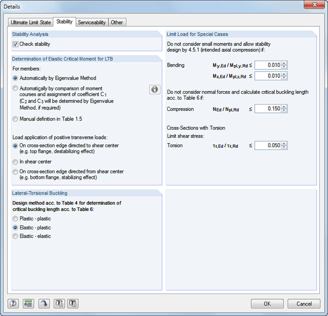
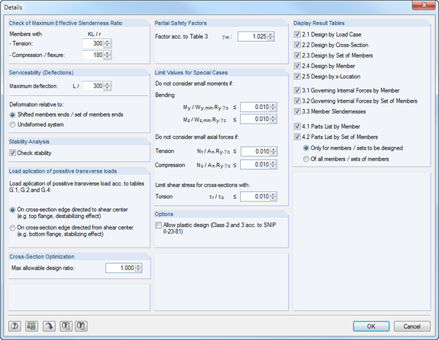
In RF‑/LTB, the design is usually performed according to the equivalent member method according to DIN 18800, Part 2. However, you can specify extensive detailed settings for the design in a separate dialog box:
Design according to Bird/Heil
Optionally, it is possible to apply the method according to Bird/Heil in the program
- the required shear stiffness Sreq
- the lateral-torsional buckling load Nki
- the critical buckling moment Mki
.
This plastic-plastic calculation method is only valid for lateral and torsional restraints with simple bending with simultaneous load introduction on the upper flange. Further requirements that must be met can be found in the program manual. In case of invalid conditions (for example, biaxial bending), RF-/LTB displays the corresponding error message. In addition, the reduction factorκM for the bending moments My can be set to 1.0 if a restrained rotation axis is present.
Non-Designable Internal Forces
It is possible to neglect non-designable internal forces and thus exclude them from the design if the quotient of the internal force and the fully plastic internal force falls below a certain value. This way, you can neglect, for example, a small moment about the minor axis, thus avoiding the method for biaxial bending.
Allowance according to DIN 18800, Part 2, Element (320) and Element (323)
Automatic determination of ζ
If you want the factor for the determination of the ideal elastic critical moment Mcr to be determined automatically, you can select one of the following types:
- Solving the elastic potential numerically
- Comparison of moment diagrams
- Australian Standard AS 4100-1990
- US standard AISC LRFD
When aligning the moment distributions, you can use the library which contains more than 600 moment distributions in tables.

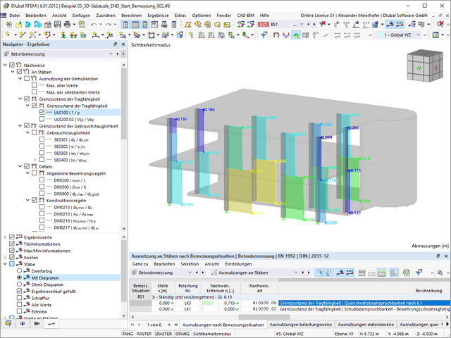
Is the design completed? Then you can lean back. The design ratios of the individual design checks (for example, ultimate limit state, serviceability limit state, or compliance with the construction rules) are displayed for you in a table. You can also find the required reinforcement listed in clearly arranged output tables. The program shows you all intermediate values in a comprehensible manner.
You can display the results of members as result diagrams on the respective member. Furthermore, you have the option to document the inserted reinforcement for longitudinal and stirrup reinforcement, including sketches, in accordance with current practice.
Select whether you want to display the results of surfaces as isolines, isosurfaces, or numerical values. In addition to the design check ratios, you can display the longitudinal reinforcement according to required, provided, and not covered reinforcement.
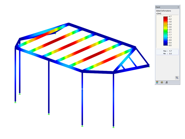
Have you carried out the design successfully? The results of the deformation analysis are now listed in clearly arranged output tables or detailed dialog boxes with info text. The program shows you all intermediate values in a comprehensible manner. Graphical representation of design ratios and deformation in RFEM allows you for a quick overview of critical areas.
Due to the results output of the design checks with all intermediate results, you can follow the calculation to the smallest detail. The complete integration of results in the RFEM printout report ensures that you obtain verifiable structural design.

When calculating the deflection limit, you have to consider certain reference lengths. You can define these reference lengths and the segments to be checked independently of each other, depending on the direction. For this, define design supports at the intermediate nodes of a member and assign them to the respective direction for the deformation analysis. Thus, the segments are created where you can define a precamber for each direction and segment.

Do you prefer it clear? So do we! That's why all performed design checks for the design standard are displayed for you in a clear way. You determine a design criterion for each design check. You get design details, which include the initial values, intermediate results, and final results, arranged in a structured way for each design check. You can find the calculation process with the applied formulas, standard sources, and results in great detail in an information window in the design details.
- Design of tension, compression, bending, shear, and combined internal forces
- Stability analysis for flexural buckling and lateral-torsional buckling
- Automatic determination of critical buckling loads and critical buckling moments for general load applications and support conditions by means of a special FEA program (eigenvalue analysis) integrated in the module
- Optional application of discrete lateral supports to beams
- Automatic cross-section classification
- Deformation analysis (serviceability)
- Cross-section optimization
- Wide range of cross-sections available, such as rolled I-sections, C-sections, rectangular hollow sections, angles, double angles (arrangement flange on flange), T-sections. Welded sections: I-shaped (symmetrical and asymmetrical about major axis), channel sections (symmetrical about major axis), rectangular hollow sections (symmetrical and asymmetrical about major axis), angles, round pipes, and round bars
- Clearly arranged result tables
- Detailed result documentation including references to design equations of the used standard
- Various filter and sorting options of results, including result lists by member, cross-sections, x-location, or by load case, load and result combination
- Result table of member slenderness and governing internal forces
- Parts list with weight and solid specifications
- Seamless integration in RFEM/RSTAB
- Design of members and continuous members for tension, compression, bending, shear, and combined internal forces
- Stability analysis for lateral-torsional buckling and buckling according to the equivalent member method or the second order analysis
- Serviceability limit state design by limitation of deflections
- Free configuration of charring time and charring rates, as well as free choice of charring sides for fire design
- Design of tapered and curved beams consisting of glulam timber
- Material and cross‑section library based on the Canadian standard
- User-defined entry of rectangular and circular cross-sections
- Automatic cross-section optimization
- Optional import of buckling lengths from the RF-STABILITY/RSBUCK module
- Detailed result documentation including references to design equations of the used standard
- Various filtering and sorting options of results
- Consideration of moisture service conditions
- Visualization of design criterion on RFEM/RSTAB model
- Data export to MS Excel
- Units metric and imperial
Do you want to perform the bending failure design? To do this, analyze the governing locations of the column for axial forces and moments. For the shear resistance design, you can also consider the locations with extreme values of shear forces. During the calculation, you determine whether a standard design is sufficient or whether the column with the moments has to be designed according to the second-order theory. You can then determine these moments using the previously entered specifications. The calculation is divided into three parts:
- Load-independent calculation steps
- Iterative determination of governing loading taking into account a varying required reinforcement
- Safety determination of all acting internal forces, including the designed reinforcement
After a successful calculation, the results are displayed in clearly arranged tables. Each intermediate value is absolutely traceable, making the design checks transparent.
- Full integration in RFEM/RSTAB including import of all relevant information and internal forces
- Design of members and continuous members for tension, compression, bending, shear, and combined internal forces
- Stability analysis for lateral-torsional buckling and buckling according to the equivalent member method or the second order analysis
- Serviceability limit state design by limitation of deflections
- Brazilian material library and cross-section library
- User-defined entry of rectangular and circular cross-sections
- Cross-section optimization with optional transfer to RFEM/RSTAB
- Optional import of effective lengths from the RSBUCK or RF‑STABILITY add‑on module
- Detailed result documentation including references to design equations of the used standard
- Various filter and sorting options of results including result lists by member, cross-sections, x-location, or by load case, load and result combination
- Consideration of moisture service conditions
- Visualization of the design criterion on the RFEM/RSTAB model
- Data export to MS Excel
- Full integration in RFEM/RSTAB including import of all relevant information and internal forces
- Design of members and continuous members for tension, compression, bending, shear, and combined internal forces
- Stability analysis for lateral-torsional buckling and buckling according to the equivalent member method or the second order analysis
- Serviceability limit state design by limitation of deflections
- Free configuration of charring time and charring rates, as well as free choice of charring sides for fire design
- South African material library and cross‑section library
- User-defined entry of rectangular and circular cross-sections
- Cross-section optimization with optional transfer to RFEM/RSTAB
- Optional import of effective lengths from the RSBUCK or RF‑STABILITY add‑on module
- Detailed result documentation including references to design equations of the used standard
- Various filter and sorting options of results including result lists by member, cross-sections, x-location, or by load case, load and result combination
- Consideration of moisture service conditions
- Visualization of the design criterion on the RFEM/RSTAB model
- Data export to MS Excel
- Design of members and continuous members for tension, compression, bending, shear, and combined internal forces
- Stability analysis for lateral-torsional buckling and buckling according to the equivalent member method or the second order analysis
- Serviceability limit state design by limitation of deflections
- Design of tapered and curved beams consisting of glulam timber
- Free configuration of charring time and charring rates, as well as free choice of charring sides for fire design
- Material and cross-section library based on the supplement to the standards ANSI/AWC NDS‑2018 and ANSI/AWC NDS-2015, including adjustment factors
- User-defined entry of rectangular and circular cross-sections
- Automatic cross-section optimization
- Optional import of buckling lengths from the RF-STABILITY/RSBUCK module
- Detailed result documentation including references to design equations of the used standard
- Various filtering and sorting options of results
- Consideration of temperature effects and moisture service conditions
- Visualization of design criterion on RFEM/RSTAB model
- Data export to MS Excel
- Metric and imperial units
- Design of members and sets of members for tension, compression, bending, shear, combined internal forces, and torsion
- Stability analysis of buckling, torsional, and flexural-torsional buckling
- Automatic determination of critical buckling loads and critical buckling moments for general load applications and support conditions by means of a special FEA program (eigenvalue analysis) integrated in the module
- Alternative analytical calculation of the critical buckling moment for standard situations
- Optional application of discrete lateral supports to beams and continuous members
- Automatic cross-section classification
- Serviceability limit state design (deflection)
- Cross-section optimization
- A wide range of available cross-sections, such as rolled I-sections; channel sections; T-sections; angles; rectangular and circular hollow sections; round bars; symmetrical and asymmetrical, parametric I-, T-, and angle sections; double angles
- Clearly arranged input and result windows
- Detailed result documentation including references to design equations of the used standard
- Various filter and sorting options of results, including result lists by member, cross-sections, x-location, or by load case, load and result combination
- Result tables of member slenderness and governing internal forces
- Parts list with weight and solid specifications
- Seamless integration in RFEM/RSTAB
- Units metric and imperial
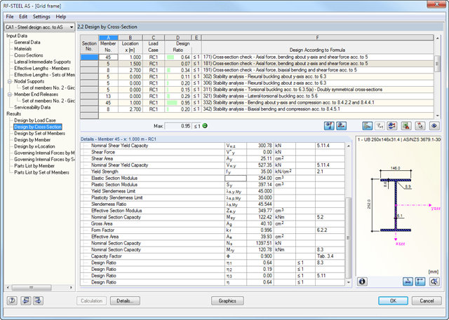
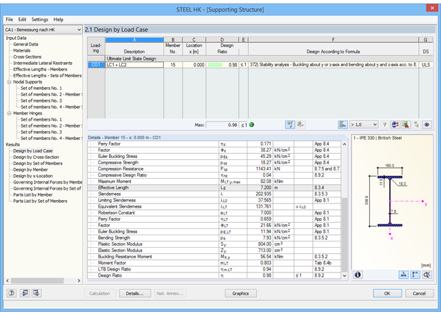
The first window shows the maximum design ratios including the corresponding design of each designed load case, load combination, or result combination.
The other result windows list all detailed results sorted by specific subject in extendable tree menus. All intermediate results along the members can be displayed at any location. In this way, you can easily retrace how the module has performed the individual designs.
The complete module data are part of the RFEM/RSTAB printout report. You can select the report contents and extent specifically for the individual designs.
- Design of members and sets of members for tension, compression, bending, shear, torsion, and combined internal forces
- Stability analysis of buckling, torsional, and flexural-torsional buckling
- Automatic determination of critical buckling loads and critical buckling moments for general load applications and support conditions by means of a special FEA program (eigenvalue analysis) integrated in the module
- Alternative analytical calculation of the critical buckling moment for standard situations
- Optional application of discrete lateral supports to beams and continuous members
- Automatic cross-section classification
- Serviceability limit state design (deflection)
- Cross-section optimization
- A wide range of available cross-sections, such as rolled I-sections; channel sections; T-sections; angles; rectangular and circular hollow sections; round bars; symmetrical and asymmetrical, parametric I-, T-, and angle sections; double angles
- Clearly arranged input and result windows
- Detailed result documentation including references to design equations of the used standard
- Various filter and sorting options of results, including result lists by member, cross-sections, x-location, or by load case, load and result combination
- Result tables of member slenderness and governing internal forces
- Parts list with weight and solid specifications
- Seamless integration in RFEM/RSTAB

Is a clear arrangement important for you? The program provides you with a clear overview of all performed design checks for the design standard. For each design check, it is necessary to determine a design criterion. There are also design details arranged in a structured way, including the initial values, intermediate results, and final results. You can laso find here an information window where the calculation process with the applied formulas, standard sources, and results is displayed in great detail.
- Design of members and sets of members for compression, bending, shear, and combined actions
- Stability analysis of buckling and lateral-torsional buckling
- Automatic determination of critical buckling loads and critical buckling moments for general load applications and support conditions by means of a special FEA program (eigenvalue analysis) integrated in the module
- Optional application of discrete lateral supports to beams
- Automatic cross-section classification (Class 1 to 4)
- Deformation analysis (serviceability)
- Cross-section optimization
- A wide range of available cross-sections, such as rolled I-sections; channel sections; T-sections; angles; rectangular and circular hollow sections; round bars; symmetrical and asymmetrical, parametric I-, T-, and angle sections; double angles
- Optional import of buckling lengths from RF-STABILITY/RSBUCK
- Detailed result documentation including references to design equations of the used standard
- Various filter and sorting options of results including result lists by member, cross-section, x-location, or by load cases, load and result combinations
- Result table of member slenderness and governing internal forces
- Parts list with weight and solid specifications
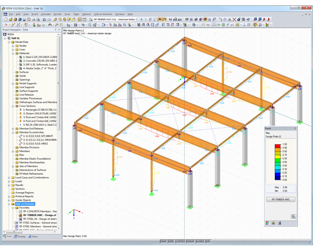
After the calculation, the module displays results in clearly arranged result tables. All intermediate values (for example, governing internal forces, adjustment factors, and so on) can be included in order to make the design more transparent. The results are sorted by load case, cross-section, set of members, and members. If the analysis fails, the affected cross-sections can be modified in an optimization process.
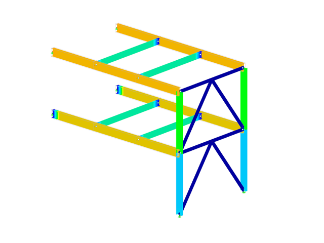
The design ratio is represented with different colors in the RFEM/RSTAB model. This way, you can quickly recognize critical or oversized areas of the cross-section. Furthermore, result diagrams displayed on the member or set of members ensure targeted evaluation.
In addition to the input and result data, including design details displayed in tables, you can add all graphics into the printout report. This way, comprehensible and clearly arranged documentation is guaranteed. You can select the report contents and extent specifically for the individual designs.
The first window shows the maximum design ratios including the corresponding design of each designed load case, load combination, or result combination.
The other result windows list all detailed results sorted by specific subject in extendable tree menus. All intermediate results along the members can be displayed at any location. In this way, you can easily retrace how the module has performed the individual designs.
The complete module data are part of the RFEM/RSTAB printout report. You can select the report contents and extent specifically for the individual designs.

You can individually define all reference lengths that need to be considered in the calculation of the deflection limit value, as well as the segments to be checked, depending on the direction. For this, define design supports at the intermediate nodes of a member and assign them to the respective direction for the deformation analysis. Thus, the segments are created where it is possible to define a precamber for each direction and segment.
- Design of members and sets of members for tension, compression, bending, shear, torsion, and combined internal forces
- Stability analysis of buckling and lateral-torsional buckling
- Automatic determination of effective radius of gyration by special integrated FEA software (eigenvalue analysis) for general loading and support conditions
- Alternative analytical calculation of effective radius of gyration for standard situations
- Optional application of discrete lateral supports to beams
- Definition of nodal supports for sets of members
- Serviceability limit state design (deflection)
- Cross-section optimization
- A wide range of available cross-sections, such as rolled I-sections, channel sections, T-sections, angles, rectangular and circular hollow sections, round bars, and many others.
- Detailed result documentation including references to design equations of the used standard
- Various filter and sorting options of results, including result lists by member, cross-sections, and x-location, or by load case, load and result combination
- Result table of member slenderness and governing internal forces
- Metric and imperial units
- Design of tension, compression, bending, shear, and combined internal forces
- Stability analysis for flexural buckling and lateral-torsional buckling
- Automatic determination of critical buckling loads and overall stability factors for lateral-torsional buckling according to Annex B
- Optional application of discrete lateral supports to beams
- Automatic local stability analysis and check of plastic design criteria of a cross-section
- Deformation analysis (serviceability)
- Cross-section optimization
- Wide range of cross-sections available, such as rolled I-sections, channel sections, rectangular hollow sections, angles, T-sections. Welded sections: I-shaped (symmetrical and asymmetrical about major axis), channel sections (symmetrical about major axis), rectangular hollow sections (symmetrical and asymmetrical about major axis), angles, round pipes, and round bars
- Clearly arranged result tables
- Detailed result documentation including references to design equations of the used standard
- Various filter and sorting options of results, including result lists by member, cross-sections, x-location, or by load case, load and result combination
- Result table of member slenderness and governing internal forces
- Parts list with weight and solid specifications
- Seamless integration in RFEM/RSTAB
Did you know? You can individually define the reference lengths to be considered in the calculation of the deflection limit value and the segments to be checked, depending on the direction. For this, define design supports at the intermediate nodes of a member and assign them to the respective direction for the deformation analysis. In the resulting segments, you can also define a precamber for each direction and segment.
The first result window shows the maximum design ratios including the corresponding design of each designed load case (load combination / result combination).
The other result windows list all detailed results sorted by specific subject in extendable tree menus. All intermediate results along a member can be displayed at any location. In this way, you can easily retrace how the module has performed the individual designs.
The complete module data are part of the RFEM/RSTAB printout report. You can select the report contents and extent specifically for the individual designs.
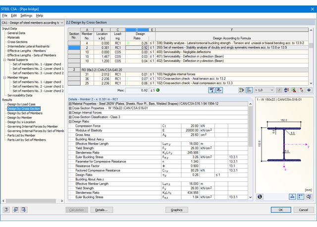
It is necessary to enter material, load, and combination data in RFEM/RSTAB in compliance with the design concept specified by the standard SANS 10162-1:2011. The RFEM/RSTAB material library already contains materials relevant for the South African standard.
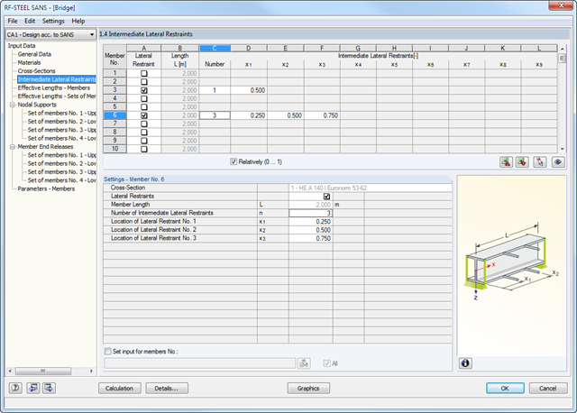
The RF-/STEEL SANS add-on module requires members and sets of members as well as load cases, load combinations, and result combinations to be designed. In the subsequent input windows, you can adjust preset definitions of lateral intermediate supports and effective lengths.
In the case of continuous members, it is possible to define individual support conditions and eccentricities of each intermediate node of single members. A special FEA tool then determines the critical loads and moments required for the stability analysis in these situations.
_(2)_(1).png?mw=640&hash=7e2297521472072f1532ffd2c7baee22c3025844)
- Design of members and sets of members for tension, compression, bending, shear, combined internal forces, and torsion
- Stability analysis of buckling and lateral-torsional buckling
- Automatic determination of critical buckling loads and critical buckling moments for general load applications and support conditions by means of a special FEA program (eigenvalue analysis) integrated in the module
- Alternative analytical calculation of the critical buckling moment for standard situations
- Optional application of discrete lateral supports to beams and continuous members
- Automatic cross-section classification (compact, noncompact, and slender)
- Serviceability limit state design (deflection)
- Cross-section optimization
- A wide range of available cross-sections, such as rolled I-sections, channel sections, T-sections, angles, rectangular and circular hollow sections, round bars, symmetrical, asymmetrical, parameterized I-, T-, and angle sections, as well as user-defined SHAPE‑THIN sections
- Clearly arranged input and result windows
- Detailed result documentation including references to design equations of the used standard
- Various filter and sorting options of results including result lists by member, cross-section, x-location, or by load cases, load and result combinations
- Result table of member slenderness and governing internal forces
- Parts list with weight and solid specifications
- Seamless integration in RFEM/RSTAB
- Metric and imperial units
- Consideration of the data from the other RF-/TOWER modules (Structure, Equipment, Loading, Effective Lengths)
- Automatic cross-section classification
- Design of triangular and quadrilateral lattice towers according to EN 1993-1-1, EN 1993-3-1, and EN 50341, including National Annexes
- Flexural buckling analysis of truss members based on the effective slenderness considering bracing and support conditions
- Design of equipment such as platforms according to EN 1993-1-1
- Clearly arranged display of results including relevant parameters in result tables
- Parts list result window
- Creation of a verifiable printout report
- Design of tension, compression, bending, shear, and combined internal forces
- Stability analysis for flexural buckling and lateral-torsional buckling
- Automatic determination of stability factors according to Annexes E, F, and G
- Optional application of discrete lateral supports to beams
- Automatic slenderness check of cross-section parts under compression
- Deformation analysis (serviceability)
- Cross-section optimization
- Wide range of cross-sections available, such as rolled I-sections, channel sections, rectangular hollow sections, angles, T-sections. Welded sections: I-shaped (symmetrical and asymmetrical about major axis), channel sections (symmetrical about major axis), rectangular hollow sections (symmetrical and asymmetrical about major axis), angles, round pipes, and round bars
- Clearly arranged result tables
- Detailed result documentation including references to design equations of the used standard
- Various filter and sorting options of results, including result lists by member, cross-sections, x-location, or by load case, load and result combination
- Result table of member slenderness and governing internal forces
- Parts list with weight and solid specifications
- Seamless integration in RFEM/RSTAB